 |
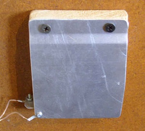
Light Switch Timer Turns Off Light in Two Minutes Electronic Circuit Schematic By Gary Novak It's not good when lights are left on unknowingly, or the switch is some distance away, maybe down in a basement. If the lights go off by themselves, it saves a lot of energy—human energy and electrical energy. This circuit turns them off in two minutes. The circuit uses momentary switches, which can be bump switches. Aluminum bump switches are extremely convenient. Any number of switches can be paralleled allowing them to be located in several places. Each time they are bumped, the timer starts over and goes for another two minutes before turning off the light. Aluminum is the best contact material to use for bump switches. It never fails to cut through grime and make contact. The worst thing to use is a solder surface. Oxide on the surface has to be cleaned off of solder about once a month with alcohol to prevent failure of contact. It's a good idea to use a small "night light" which is left on continuously nearby, so a person isn't left in total darkness when the light goes out. The best night lights nowdays are LEDs. Wal-Mart sells LEDs which give off 40 watts of light equivalent while using only 1.5 watts of electricity. They cost $5 but last almost forever. The power supply starts with a 12V, low amperage transformer. Almost any size could be used, but 12V is good for driving relays with CMOS. A 12V relay is good for keeping current levels low, as 5V relays use more current. Since the rough voltage starts at 18V and comes down a little with a load, a resistor is used in series with the relay coil. To calculate resistor size, measure the resistance of the relay coil, and divide it into 12V to get the current. If the rough voltage drops to 15V with the coil on, then put 3V across the resistor. Divide the 3V by the current to get the resistor size. Then determine the wattage required for the resistor by multiplying the current times the 3V. Sometimes, a half watt resistor may be needed. Here, the CMOS circuits use 5 volts. They are specified for 3-15 volts. | |||||

Circuitry
|

|
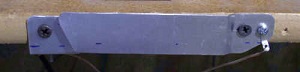
The timing circuit starts with an oscillator. Schmidt triggers are the simplest and most reliable way to create oscillators with CMOS circuits. They also provide inverters, which are usually needed in the circuitry. The oscillator is set at a frequency of 136 Hz. The square wave goes into a 4020 for 14 stages of division and exits the 3 pin at 120 seconds per cycle. However, the first 60 seconds will be down voltage, and the next 60 seconds up. So the transition must occur while the 3 pin is coming back down. Since this signal goes into the clock of a flip flop, which is plus edge triggered, an inverted must be used to convert the downward transition of the 4020 3 pin into an upward transition for the 74C74 clock. The bump switches pull the preset (4 pin) of the flip flop down, which forces q (5 pin) high and turns on the light. Upon release, preset is pulled high with a resistor, which is its inactive position. What also happens when the switches are bumped is that an inverter sends a high pulse into the 11 pin of the 4020, which resets it back to zero and causes the count to start over. This way, you don't have to wait for the cycle to complete and the light to go off before adding more time. The 6 pin of the flip flop (q bar) also sends a high pulse to the 4020 11 pin, but not until the clock pulse turns off the light. This holds the light off until a switch is bumped. Two diodes function as an OR gate going into the 11 pin of the 4020. This is much easier than putting an actual OR gate on the board. The diodes allow a high pulse to reset the 4020, while a resistor holds the reset pin off otherwise. The 2 pin of the flip flop is called data input. This means the clock transfers it's signal to q (5 pin) on the up pulse of the clock. Since D is grounded, q goes down on the clock pulse and turns off the light. The clear input of the flip flop (1 pin) is held high, which is its inactive position. If you want to increase the time, the oscillator can be slowed down by increasing the size of the capacitor and/or the resistor. Or another 4020 can be added in series. There are 11 additional output pins on the 4020 to make smaller steps, each reducing the time by one half. The 0.1µF capacitor across the switches removes noise from the line. Diodes are sometimes used across a relay, as shown, to prevent voltage spikes from the relay from damaging the transistor. But in this case, the MPSA13 is so rugged, and the relay so timid, that I omit the diodes. Below is what aluminum bump plates look like on a "one by four" and the edge of a shelf. There needs to be enough over-hang on the aluminum to attach solder lugs.
|