NOV79

Background Sound Synthesizer

 
Electronic Circuit Schematic

Free Electronics Plans on the Internet

By Gary Novak

Electronics Home Page

Introduction

Background sound can be of value in covering up external noise and relocating the ambient in one's surroundings. Using music for that purpose has some disadvantages including its own distractions, nonuniform result and quite a bit of expense. Synthetic sound can be easier to listen to on a long term basis.

This synthesizer produces tunable frequencies with rhythm and resonance. It basically takes harmonic distortion, maximizes, tunes it and adds a beat frequency, which can be omitted.

The easiest sound to listen to long term is low frequency with complexity. The synthesizer produces a good amount of complexity at low frequency. It can be tuned with a heavy beat to sound like a train locomotive idling, or it can be smoothed out to sound more uniform and somewhat musical.

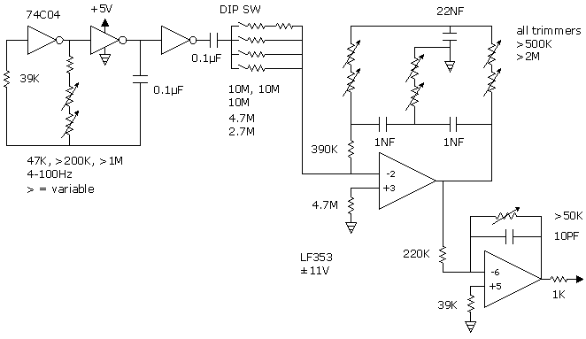
The basic circuit is a low pass and high pass filter in the feedback loop of an op amp. It generates its own oscillation with harmonics, which are tunable. The circuit has been shown in electronic data books for some time, being referred to as an "electronic bell." With a momentary switch, it makes a ping which resonates. It doesn't sound like a bell, and it drifts out of tune too easy to be used reliably as a ping.

Drift is a problem with the circuit, because slight changes in frequencies have a great effect upon the beat frequency of a resonant circuit. Therefore, for long term use, the device should be temperature stabilized. This is done by heating the aluminum box with power resistors to about five degrees above room temperature and using a diode as a temperature sensor for measuring and controlling the temperature. The sound is then totally free from noticeable drift.


Figure 1. Synthesizer Circuit. (image page)


This device was designed for trimmers set in a fixed position in an enclosed box. Potentiometers could be used on a panel for more convenient tuning.

The circuit should be breadboarded for preliminary testing. Connect it to an amplifier and listen to it while tuning. You may decide to focus on low frequencies only, and then the large trimmers might be replaced by fixed resistors.

To experiment with sounds, add noise. This is done by connecting a wire to the 2 pin of the op amp. The other end could be wrapped around a line cord, or connected to a metal object that picks up noise. Add resistance with it, if the noise is overwhelming.

Inverters function as an oscillator for an input beat frequency. The range tunes down to 4 hertz. If lower frequency is desired, replace the oscillation capacitor and coupling capacitor with 0.5µF.

A DIP switch on the board allows the input beat frequency to be weakened or strengthened. For little or no beat frequency, leave all switches open.

At low frequencies, the op amp usually oscillates to the rails. The supply voltage is ±11V, because low frequencies oscillate about right at that voltage. The voltages could be varied, if testing indicates a reason to.

An op amp is used for gain reduction at the end. Since low frequencies will osocillate with more voltage than high frequencies, the desired amount of gain reduction will depend upon frequency. The output voltage is set at something typical for audio amplifiers. The adjustment is easier to make by listening than using a scope, but ±0.5V is optimum for audio input.

You should not hear any noise when the heater turns on. If you hear heater noise, check the grounding. Sometimes more than one ground connection to the box will create edies that pick up noise.


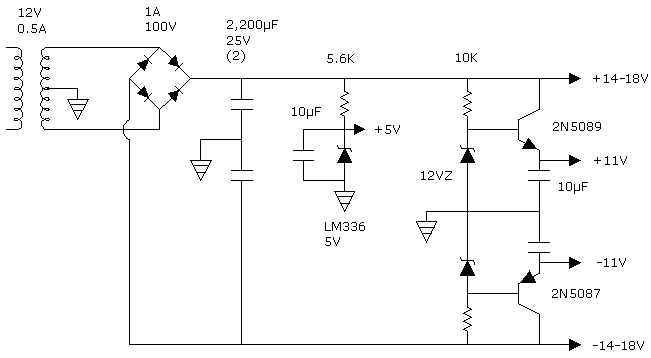
Figure 2. Power Supply. (image page)


The transformer is oversized, which allows more heat to be added, if a larger and noninsulated box is used. You won't find an air core transformer, so go ahead and use iron core.

The 11V output transistors can be anything. They are not protected, so it is not a good idea to do too much messing around on the board. On a breadboard, use some other source of voltage. If an experimental device is being constructed, use regulators. 8 to 12 volt regulators will suffice.


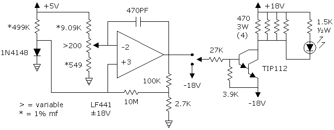
Figure 3. The Heater. (image page)
 

The heating is done with four power resistors, 470 ohms, 3 Watts each. They are controlled by the darlington transistor, TIP112. They are located on the bottom of the box, two on each side. They are held up against the edges with a piece of aluminum which is bolted to the bottom.

The temperature sensor is a 1N4148 diode. A diode is the best temperature sensor there is for most electronic purposes. It has about half as much sensitivity as the best thermistors, which is not bad; and it is totally linear, unlike thermistors. It also has the advantage of being smaller in size, which reduces heat capacity and speeds up response time.

You should not have to calibrate the diode for this purpose. Calibration is done in stirred oil with a reference thermometer. I did calibrate the diode which I used. It's slope was 2.747mv/°C. In the circuit shown, it produced 367mv at 30°C. Adjustment range was 30-60°C, 369-280mv. My trimmer only had 165 ohms.

Diodes will vary a few percent. If you have some other type, try it on a breadboard. Touch it to heat it a few degrees and see if the LED goes on and off. You might solder the 9.09K resistor onto the top of the board, so you can make range adjustments if necessary without taking out the board.

The optimum setting would be on for about twenty seconds every two minutes. Equilibrating is very slow with this circuit. A cold device might take a half hour to equilibrate. The tone will change during equilibration.

diode sensorThe diode should be located about 20 to 30mm from one of the heating resistors for good response time. I hold the diode on the bottom of the box by running a thin strip of aluminum or flexible can tin over the top of it with a little curvature and bolting it down. 30 gauge kynar wires are used to reduce heat capacity and stess forces. The diode is coated with heat sink grease.
The op amp has a small amount of hysteresis on it. Histeresis is created through noninverting feedback, which creates a difference between cut-in and cut-out voltage—in this case, about 0.8mV. It stablizes response preventing oscillation.

A switch at the output of the op amp allows the heater to be turned off.


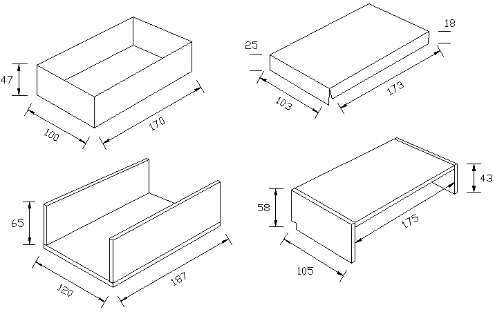
Figure 4. The Box. (image page)
 

The box could be made of 0.063 inch thick aluminum for good heat conduction; but it would be hard to bend; and therefore, 0.050 is preferable. The lid can be 0.032 or 0.040. (There are 25.4mm per inch.)

The box snaps together without attachments. It then sits in a wooden box for thermal insulation. The line cord goes through where the square notch is. On the other end, the wood is elevated a little for an RCA jack which carries the signal out; and alongside it is the LED.

The wood is quarter inch thick (6mm). Various exotic woods can be found at Craftsman Wood Service Company. The dimensions on the wood are the sizes that the pieces are cut, which is sometimes inside dimension, and sometimes outside dimension. Dimensions are in millimeters.

I put rubber feet under the aluminum box. There's plenty of space.

The printed circuit board is 95x115mm, which leaves enough space for the transformer. The board is elevated above the heating resistors. Aluminum brackets attach it to the sides. Keep the bolts for the brackets low enough for the lid to go on; and put the RCA jack and LED under the PC board.

Electronics Home Page


Gary Novak TOP

Science Home