| NOV79 |
|
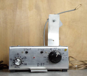
Thermostat Circuit
(image page)
|
|
Power Supply  |
|
The diode temperature sensor is connected to shielded cable, which could be attached to a bracket on the box, or it could go out some distance for sensing close to the source of heat. Leave the leads long on the diode sensor, because the metal improves the speed of the response. Bend one lead 180 degrees, or both leads 90 degrees. The easiest way to calibrate the diode sensor would be to determine the crossover point at room temperature after construction, and assume the slope to be 2.64mv/°C. At 20°C, the diode for the prototype was 392.4 mv, but that quantity can vary somewhat. Correlating with room temperature would be more reliable, if the air is somewhat stable and nonconvecting. For more precision, cool some cooking oil in the refrigerator and find a thermometer that can be immersed in it along with the sensor. Leave the oil in one container, because mixing creates heterogeneity in oil. Only two points are needed for the slope, because diodes are totally linear in their temperature response. If this is done after construction, short the 2 pin and 6 pin of the op amp with a jumper creating a unity gain buffer and measure the voltage on it. I put resistors vertical and leave the exposed lead on the voltage which is most apt to be measured. For precise measurement before construction, use the same voltage reference and resistor, and use an op amp buffer for measuring the diode voltage. The referencing resistors that I used were 3.45k on the plus side, and 1.60k on the minus side, with a 250 ohm potentiometer. The reference voltage was 1.238v. The range was 12-28°C. You might want to use a wider range, if calibrating is not done before construction. You might also want the resistors to be solderable from the top of the board. A FET op amp must be used in the circuit, because it does not draw excess input current during saturation. A low power FET, such as LF441 or TL061, is used for low current resulting in low drift from heating. The frequency of the oscillator is 273 Hz, or 3.662 msec per cycle. It is reduced by 16,384 in the 4020 resulting in 60 sec cycles into the 4017. The 3 pin of the 4020 goes high in 8192 counts. If two minutes per interval is desired, reduce the oscillation frequency to 136 Hz by increasing the size of the cap and/or resistors. The oscillator should be tested on a breadboard to determine resistor size, because there can be a lot of difference in threshold voltages for different brands of schmitt triggers. If you don't have a frequency counter, run it through a 4020 and time the 3 pin for 60 seconds. The outputs of the 4017 go into a rotary switch for selecting on-time at 1 min intervals. One minute is the 2 pin, 2 minutes is 4 pin, etc. Zero is the signal from the collector of the 2N5088. At this setting, relay-on follows sensor-on. The LED for the relay follows the LED for the sensor. For this, connect the arrow from the collector to a position on the rotary switch to be used as zero on-time. The reason for using a 4013 is because it resets on the high pulse from the 4017. The 6 pin is called set, and the 4 pin is called reset. They do opposites on high pulses. Q output (1 pin) goes high with 6 pin high. The 6 pin overrides the 4 pin, but only while it is high. Therefore, if the sensor is still on at the end of a cycle, reset occurs, and a complete cycle starts again. If heat up of the sensor is slow, two or more cycles might occur. Using short cycles is suggested for a slow heating sensor. But locating the sensor for rapid response works best. The capacitor on the stop switch causes a stop signal to activate when powering up. The 1K with it reduces spark on the switch, and the 47K reduces reverse current into the OR gate when power drops. Be sure all unused inputs for the digital chips are connected to the plus or minus rails. For output connections from the 4017, I use loops of 22 gage wire. They have both ends soldered into the board. Bus wire goes from there up to the rotary switch. The collector of the darl goes out for driving an external relay for electric heat. A resistor attaches to the relay. If you don't want the internal relay wearing out while driving an external one, you could put a switch on it, or a connection solderable on top of the board could be used. The Box:
|