 |
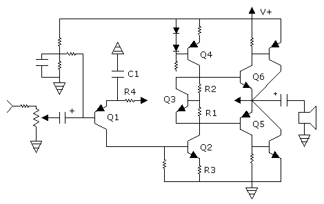
How Audio Amplifiers Work by the usual design Here's an ultra simple description of the usual design for audio amplifiers. The complexities are infinite. As one expert said, you might design an audio amplifier and find that it is a dud. In other words, the problems might be unsolvable. The primary problem is instability due to high voltage gain at the output. Noise pickup is also a problem due to the gain. The output transistors are Q5 and Q6. To increase curent handling, boosters are added. Darlingtons can be used for Q5 and Q6, and then boosters are not needed. There must be a small amount of quiescent current through the output, typically 5-8mA. This means Q5 & Q6 are slightly open. They are opened by Q3, which has approximately 1.2V across it, as set by R1 and R2. Both resistors are about the same size, but a trimmer is used with R2 to set the quiescent current. The size of R1 and R2 is such that about one fifth as much current goes through them as through Q3. If darlingtons are used at the output, there is 2.4V on Q3, and R2 is about three times as large as R1. The purpose of Q3 is to function as a voltage regulator. Q2 sends the signal up the column. Its collector must get close to the rails so as to not waste voltage which would increase heat. The system is tested by rolling the voltage up and down on Q2 and watching for linearity. There should not be more than about 10 or 20% variation in output quiescent current from rail to rail. A major problem is in the fact that Q2 must be close to the lower rail so as to not waste voltage. The result is that it produces very high voltage gain. The voltage gain is approximately the resistance at the collector divided by the resistance at the emitter. The resistance at the collector is replaced by a current source (Q4), which is the equivalent of infinite resistance. The components will reduce the gain from infinity to something like 50,000. The goal is to reduce it some more, which is what R3 does. It would typically have 1 or 2 volts across it. The current through the source might be 5-8mA Q1 not only functions as an input transistor, it also creates inverting feedback, which centers the output. (The arrows from it and the output are supposed to be linked together.) R4 might typically be 15K and have 5V across it, as determined by the size of the resistor at the collector of Q1. So the biasing circuit at the input of Q1 would then set the input voltage at about 5.6V bellow center. If for example, the supply voltage was 24V, and R4 had 5V across it, the input bias would be set at 6.4V, and the output would center at 12V. C1 hardens the emitter creating some gain on Q1. The gain can be reduced by adding resistance in series with the capacitor. The cap might be 100µF. Keeping the output from oscillating is usually difficult. Capacitors are often used in various places to reduce the speed for that purpose. Sometimes inductors are used at the output to increase stability.
|
|
|||||||||||||||||||||||
