 |
New Audio Amplifiers With Current Amplifier Outputs
Current amplifiers drive speakers.
The perfect way to drive inductive loads. Introduction
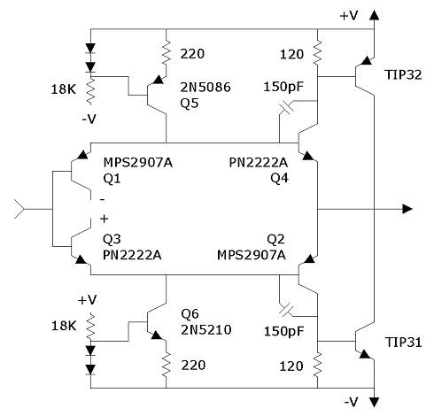
The current amplifier might look complex, but it is simpler than usual amplifier outputs. It consists of emitter followers and current sources—the simplest and most reliable circuits in transistor electronics. Emitter outputs track the base with a small offset. A total absence of variation creates reliability and makes designing easy. The current amplifier output isn’t just a different circuit; it is the only way most loads should be driven, particularly hard to drive inductive loads, due to its stability and reliability in addition to its ease of design. One of the reasons why the current amplifier wasn’t used in the past is because the betas (current gains) need to be matched for the small transistors. In fact, there was probably no realization that matching betas would make the circuit work. Matching betas should be automatic with integrated circuits, and it is very easy to do for hands-on work. There is a need for low cost audio amplifiers which are free from noise and distortion. But they don't exist, because removing noise and distortion is expensive with the usual designs due to a problematic output. With this new design, current amplifiers solve the problem. They remove noise and distortion at low cost and eliminate the embroilment of designing over an oscilloscope. These amplifiers can be drawn up on paper and constructed without an oscilloscope. The problem with the usual design is in the output. The output drivers were integrated into the amplifier in a way which produced an inadvertant but unavoidable high voltage gain. The high gain picked up noise and created an oscillation which was difficult to stabilize. The current amplifier solves the output problem by following the voltage amplifier with a circuit which gains the current (and hence, load driving capacity) without internal voltage gain. The current amplifier is low in noise because of the absence of internal voltage gain. It is also low in distortion because of its high speed. It will get all of the speed and power out of transistors that they can handle. It will ring at 20-40 MHz, when boosters are used with it, as high speed circuits often do; but that problem can be solved without affecting the audio range. (Ringing is a high frequency oscillation, where inductance in wires stores the energy.) Without boosters, ringing does not occur. This design is too fast for harmonic distortion. Circuits cannot oscillate below their maximum speed. Harmonic distortion is only a concern with usual designs because their maximum speed is in the audio range. The audio amps with the worst harmonic distortion will not function above 5 or 10 KHz. These amplifiers are easy to construct and versatile. Most importantly, they allow variable gain, which is a must for audio amplifiers, though it seems to have been nonexistence in the past. Generally, instability would not allow variable gain. Variable gain allows low volume without over-sensitivity on the volume control. Multi level volume controls would not do the same thing, because they would not reduce the noise like reduced gain does. Reduced gain can convert a 100 watt amplifier to a 5 watt amplifier in all respects except the size of the box. These plans show prototypes for three amplifiers: 10W, 32W and 75W per channel, with a variety of options. The 10W amplifier uses op-amps for voltage amplifiers, which limits the design to 36V when using normal op-amps. The 32W amplifier uses the same circuits in bridge form, which gets about four times as much wattage from the same voltage. The 75W amplifier uses a 90V power supply. Output transistors are not generally available for circuits above 100V; however, the 100V ones usually test out to 180V or more, so I wouldn't be afraid to use them at 120V. The starting point in designing an amplifier is to find a transformer with a voltage to amperage ratio suitable for the speakers, which are usually 8 ohms. Transformers should be toroids for large audio amplifiers, because they produce less heat and noise and take up less space. Even the 75W amplifier does not require a fan, because it uses a toroid transformer and a large aluminum box.
I use the 10W amplifier for laboratory purposes. It is something everyone needs for general purposes such as a television amplifier. It has a flat frequency response of 5Hz to 400kHz in low gain, 200kHz in high gain. However, at full load (2 amps), cheap power transistors will not function that fast. If they fail to complete a cycle, current flows between them, and they burn out. At 2 amps, their maximum speed is around 80kHz or more, but 50kHz is a safer limit. Lighter loads allow higher speeds. Boxes should be hand made from aluminum sheet metal to optimize design. Small boxes use a thickness of 0.040 inches (1 mm), larger ones, 0.050 or 0.060 inches (1.3 or 1.5 mm). These amplifiers use split power supplies, which allows output and centering capacitors to be eliminated while delivering the same power to the speakers. Where split supplies are not available, such as automotive, a technique is shown which allows the same circuitry to be used.
Electronic switching is used with the 75W (90V) amplifier. This means soft-touch buttons are used to vary 8 gain positions or input channels. It is an ideal design, as variable gain is used as often as the volume controls. But it is tedious to construct requiring about 40 chips and 300 hrs of work or more, depending upon research. Plan to make a lot more diagrams than are shown here and do a lot of testing. If you can't undertake such a Herculean task, use rotary switches for variable gain and toggles for the other switching. Slide switches tend to be unreliable but not out of the question when you can replace them easily. Volume controls are customarily put on the noninverting inputs, but in these amplifiers, I put them on the inverting inputs, which minimizes gain, eliminates common mode voltage and produces a logarithmic taper. These are miniscule effects, and the noninverting input can be used except for the quad input amplifier. I do not normally put tone controls on an amplifier, because they have little relevance, they add distortion, and they clutter the circuitry and front panel. But they were added to the 75W amplifier to demonstrate their use. The ones used are of highest quality for linearity and low distortion. A bypass switch is used with them, so the position doesn't have to be watched; and it eliminates any question about the purity of the sound. Tailoring in tone controls well requires much work with an oscilloscope, signal generator and frequency counter. It is not something that can be done on paper. The tone controls designed here can be transplanted to any amplifier, since they have their own supply voltages. To test them, put them on a breadboard and connect them to an amplifier and listen to them. You can use any type of signal with these amplifiers. Among the best signals is earphone jacks, which is what you would use for a computer. If nothing else is available, speaker outlets can be used. I have used the 90V amplifier for twenty years, on continuously, and it is flawless. Table of Contents | How Amplifiers Work
|
|
|||||||||||||||