Measuring small distance has been one of the most intractable problems in electronics. The Femto Capacitance Meter provides a practical method of measuring in the millimeter range. The prototype measuring device described here uses circuitry similar to the Femto Capacitance Meter, which is described in detail here: (meter).
Below are recorded results when using a ruler to measure between plates. The frequency here is 233 kHz.
| capacitance |
distance |
theory |
|
| 2.00 pF |
1.5 mm |
1.39 mm |
|
| 1.4 pF |
2.0 mm |
1.98 mm |
|
| 0.90 pF |
3.1 mm |
3.08 mm |
|
| 0.65 pF |
4.1 mm |
4.26 mm |
|
| 0.50 pF |
5.0 mm |
5.54 mm |
|
| 0.40 pF |
6.2 mm |
6.93 mm |
|
| 0.30 pF |
7.5 mm |
9.23 mm |
|
| 0.25 pF |
8.5 mm |
11.08 mm |
|
| 0.20 pF |
9.8 mm |
13.85 mm |
|
| 0.15 pF |
11.3 mm |
18.47 mm |
|
| 0.10 pF |
14.0 mm |
27.70 mm |
|
| 75 fF |
15.3 mm |
36.93 mm |
|
| 50 fF |
17.8 mm |
55.40 mm |
|
| 30 fF |
20 mm |
92.30 mm |
The formula for calculated theory is this:
| pF = |
0.00882 x area of one plate (mm2) |
![]() |
| distance between plates (mm) |
| |
The graph is shown below.
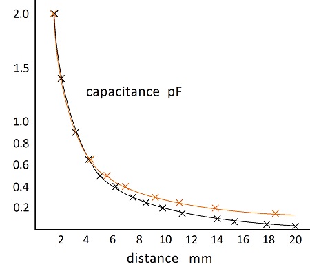
There is an asymptote as distance approaches zero, and it limits the minimum distance. With plates which are 20 mm diameter, the asymptote gets too steep for effective measurements at less than 2 mm between plates. The asymptote can be shifted left for shorter distances by using smaller plates.
The measured values start to drop below theoretical values at about 0.5 pF due to stray capacitance to the grounded aluminum in the vicinity. There is 75 mm of space between the plates and bottom of box and sides.
The right side of the graph is usable below 0.5 pF if stray capacitance is accounted for. This could be done through zero adjust and gain adjust on the amplifier. Or an environment could be used where there is no stray capacitance.
Shielding is not needed if the ambient energy in the air is stable enough for the purpose. Turning on a light in the vicinity of the above photographed measurement would decrease the measurement by about 3 fF due to 60 cycle energy in the air.
Apart from the ambient energy, the limiting factor is drift due to temperature change. My preliminary estimate is that the measurement increases by 2 fF for each degree centigrade of ambient temperature increase. While photgraphing the above measurement of 100 fF, the measurement varied by about 0.5 fF in ten minutes.
Here’s the graph when using a frequency of 45 kHz:
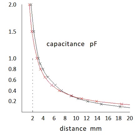
The offset at the top of the graph is a result of the plates having an apparent diameter greater than 20 mm. This is due to metal soldered onto the back of the plate. However, this effect was not noticeable at 233 kHz. This means the wave went around the plate more effectively at the lower frequency. Therefore, the higher frequency may be more practical, though it is more demanding to produce.
Power Supply
T-Wave Generator: 45 kHz
Current-to-Voltage Converter: 45 kHz
T-Wave Generator: 233 kHz
Current-to-Voltage Converter: 233 kHz
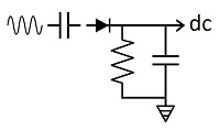
The op amp which picks up the signal, and its feedback resistor and capacitor, is attached to the metal plate using epoxy. Attaching an integrated circuit to the plate will allow smaller plates and improve results.
When absolute values are not being measured, such as accelerometers, the number of components could theoretically be reduced to three—a diode, resistor and capacitor—while the input wave could have almost any shape. A high frequency would increase sensitivity. A computer clock could probably be used for an input wave. A trimmer resistor would probably be used to adjust the dc output.
With three components and a high frequency wave, sensitivity could go into the zeptofarad range.