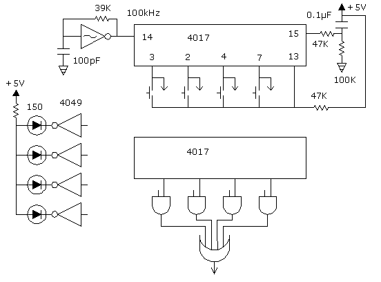
4017 Latch Circuit.
(X)
|
|
Each momentary switch functions independent of the others, so any sequence can be used. The 3 pin, which is zero, functions like the others, except that it is the reset position. This allows a controlled outcome when the power bounces off and on. The 15 pin resets with a high voltage. It has a capacitor on it, which causes it to reset upon turn on. If this function is not desired, ground the 15 pin. The 13 pin runs the counter when low and stops it when high. A resistor holds it high, until a switch is pressed, which causes the counter to run, until the selected position goes high. The arrows coming off the switches go to two places: the AND gates and the inverters which drive LEDs to indicate which switch is on. All ten positions can be used by adding more AND gates and related components. The lower 4017 is not an essential part of the circuit. It is an example of how to use it with the thermostat circuit shown elsewhere. The rotary switch in that circuit is replaced with the 4017 latch. Any square wave with enough speed and the right voltage can be used at the 14 pin. I have not studied the minimum speed for the square wave. One kilohertz would be a safe minimum. The maximum oscillator speed is anything the chip will handle. The output of the quad OR gate goes to whatever circuit is being controlled, which would typically be a flip flop.
|