Page 6, Audio Amplifiers.
 
Amplifiers


Electronics Home
Page 6
▼▼▼
 

New Audio Amplifiers
 

Bridge Amplifier

A bridge amplifier produces about four times as much wattage from the same voltage as a regular amplifier. It does that by controlling both sides of the speaker instead of just one side. Regular amplifiers operate with one side of the speaker grounded; so only half of the power supply is being used at any time. The bridge amplifier applies that unusued voltage to the other side of the speaker. It does that with another amplifier which is inverted from the first. The voltages on the two sides of the speaker then move in opposite directions.

The only advantage of the bridge amplifier is lower voltage. But that's enough of an advantage to justify it at high wattages, particularly since home builders cannot get parts for systems above 100V. Op amps can then be used at fairly high wattages. In the past, amplifiers were too difficult to produce to put twice as many in a box for bridging. Now they are easy enough to produce to make bridge amplifiers practical.

Mechanical switching was used with the bridge amplifier in order to evaluate it. The rotary switch for gain select is not convenient; but considering that there was no gain select on previous amplifiers, it's acceptable. The rotary switches are 2P6P allowing one side to be used for LEDs. The LEDs could be omitted, if the rotary switch position is visible enough.

The op amps were again zener regulated to ±18V, because the transformer voltage peaked a little over their specifications. I try to keep circuits within specifications, but you could get by with some overvoltage on the op amps.

A preamplifier was used for gain select, so the main amplifiers could be lower in impedance, and the volume control would be easier to design. Using a preamp is easier than not for these reasons. The preamps and incoming signals were put on a lower board, so they could be gotten close to the volume controls easier without crowding.

The current amplifiers were put on the back panel to reduce the maze of wires to the boosters. Their quiescent current is 4mA; and the slew rate is 18V/µS.

The output jacks for the bridge amplifier have to be the insulated type; so leave plenty of space for them. The input jacks take up less space if they are the individual type which attaches directly to the aluminum.
 
The bridge amplifier does not need output capacitors, even if the power supply is nonsplit. However, differences in reference voltages would create an undesireable offset; so the same centering capacitor should be used for both halves of one channel, but use a different one for the other channel to prevent crossover.   (Figure)

Bridge Amplifier Circuits


  Contents

     Page 1

     Page 2

     Page 3

     Page 4

     Page 5

     Page 6

     Page 7


Power Supplies

Transformers produce a peak voltage of a little more than 1.4 times their rated voltage which is rms. The filtering capacitors capture the peak voltage; but that voltage drops rapidly to the rms level with a load. There is some ripple at the rms level, because filtering capacitors are not thorough at heavy loads. A typical ripple on the filtering capacitors would be 10 to 20% at full load. Oversize capacitors reduce the ripple somewhat. The capacitors should be atleast large enough to handle the current according to their ripple current ratings, which are given in some catalogues.

Voltage regulators are not generally used for the main load with audio amplifiers, because minimizing the heat is desireable, and regulators function by burning away some of the power. However, it is common to use regulators for the light circuitry.
 
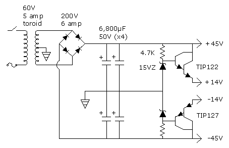
The three power supplies used for these amplifiers are shown below.   (Figure)

Power Supply Circuits (watts per channel)

10 Watt Amplifier


Bridge Amplifier (32W)


90V Amplifier (75W)

The transformer for the 10W amplifier is underloaded, as it only sees about I amp at full load. With the light load, the voltage does not drop all the way to its rated level; and the speakers see about ±13V peaks, even with a volt across each booster transistor.

The bridge amplifier uses about the same power supply, except that two transformers are-paralled for doubling the amperage. The polarity must be watched when paralleling transformers. If in doubt, apply voltage and compare outputs. The 15,000µF filtering capacitors are a little larger than they would have to be. A size of 10,000µF would have been within specifications for the 4 amps of current.

These two transformers produce a lot of heat, which is a problem for the bridge amplifier. I had to put fins on the sides of the lid for additional dissipation. For this reason, it would be preferrable to use a toroid transformer for the bridge amplifier.

The 90V amplifier uses a toroid transformer (from Active Electronics). At high wattages, toroid transformers should be used, because they are far more efficient than rectangular transformers. A lot of transformer heat under the aluminum is not easy to handle; but here it is no problem. The toroids waste almost no energy with light loads; so using a high powered amplifier on a table top for quiet listening is very practical.

Again, this transformer is a little underloaded; and the speakers see ±35V peaks with full load on both channels. The transformer load is a little more than 3 amps. So there is more than twice as much capacitor filtering as would have been required, unless parallel loading of the speakers increases the amperage.

Voltage regulators are used for the light circuitry. They are set at ±8V for the op amps. Diodes then drop it to ±7.4V for the CMOs. Another 0.6V drop is used for the protection diodes infront of the first four CMOS switches. But instead of just using another diode on each side, which would have allowed the signal to pull against resistors, transistors buffered the ±6.8V, as shown.

Ahead of the regulators, the voltage was dropped to ±l5V with transistor buffered zeners. The regulators could have handled the higher voltage; but the heat was reduced on them, because the lower one handles quite a bit of current for the LEDs.

The drift on the regulators probably would not have precluded their use for setting the input current for the quad input amplifier. But since the regulators are adjustable, excessive or unwitting variations in the amplifier input current could have resulted; and therefore, zeners were used along with the regulators for the quad input amplifier.
 
Shut Off Mechanism

The on-off switch controls the ac line voltage; but not the dc. Therefore, the filtering caps are drained through a power resistor which is switched with the ac. Reverse diodes from supplies to ground protect against reverse voltage. Regulators are protected from reverse current with diodes, as shown; or the current can be drawn through their outputs.   (Figure)


Headphones

The headphone jacks were usuallly on the front panel. A switch near the speaker outputs allows the speakers to be turned off for headphone listening. An 1/8" stereo jack was used for the lightweight headphones; and a 1/4" stereo jack for regular headphones.

The wattage for the lightweight headphones was resistor limited to 100mW for protection. Their expected impedance is 35W. For the regular headphones, the wattage was limited to 500mW. Their expected impedance is 8W. Current limiters were not used for the headphones, because they would have peaked out too fast resulting in nothing for range on the volume or gain. The protection circuits are aligned upon peak voltages rather than rms voltages, because clipping results in a squaring of the wave.

With the 10W amplifier, a 270W, 2W, resistor for each channel went from the output of the current amplifier to the 1/8" jack. A pair of 56W, 5W, resistors are used for the 1/4" jack. The bridge amplifier uses the same procedure; the headphones are not bridged.

For the 90V amplifier, separate current amplifiers were constructed for the headphones, so the full 90V range would not be required. Otherwise, the resistors would have had too much wattage on them. The current amplifier uses ±8V; and the incoming signal is further limited to ±5.7V with zener diodes back to back. The resistors to the 1/8" jacks are 75W, 1W, and to the 1/4" jacks, 15W, 2W. Two jacks for each size were used. The tip of phone plugs is left side.

The power transistors (boosters) are placed on the board without heatsinking.   (Figure)
 
Headphone Current Amplifier


Calculating Wattages.

Almost all watts in electronics are converted to heat; and that heat has to be accounted for.

Wattage calculations for the output analyze one half of the wave. The effective voltage (called rms) is 0.707 times the peak voltage, since audio signals are sine waves. The peak voltage is analyzed from one side to ground; and the voltage drop across the transistor is subtracted. It is usually 1 or 2 volts with the current amplifier. After the rms voltage on the speaker is determined, it is divided by the 8 ohms of the speaker to determine the current. This current determines the wattage; but it is not the current that the transformer sees in total, because it only goes through half of the transformer. So the transformer current is one half this amount; but it is again doubled because of the other channel. The wattage for the channel is the current times the rms voltage.

For example, the 10W amplifier produces ±14V under a full load. The speakers see ±13V peaks, because there is a volt across the boosters. The rms voltage is 0.707 x 13 = 9.2V. The current is 9.2/8W = 1.15 amps. The wattage per channel is 9.2 x 1.15 = 10.6W.

With the bridge amplifier, both sides of the power supply operate simultaneously. The amplifier voltage under full load is about 25V. The speaker sees about 23V, at an rms of 16V. Therefore, an 8W speaker uses 2 amps. Two amps at 16V is 32 watts per channel. The transformers get 2 amps from each channel for a total of 4 amps.

The 90V amplifier at full load ripples between ±38V and ±44V, depending upon frequencies. The speakers see a peak of atleast ±35V. The rms is 24.7V. The rms current for an 8W speaker is 3.1 amps; and the wattage is 76.5W per channel.

Actually, wattage calculations apply to the resonant frequency of the speaker. At other frequencies, the current lags or leads the voltage, which lowers the wattage.

This result shows up when the current limiter is allowed to clip the output. The waves are not flattened on top but are sloped along one side. Since the voltage is not maximum while the current is maximum, the actual wattage is not as high as the calculations indicate. But the calculations provide relative values in a simple way for making comparisons.


page seven  |   page one  |   contents

 
    1        2        3        4        5        7    
 

Electronics Home Page TOP     


  Contents

     Page 1

     Page 2

     Page 3

     Page 4

     Page 5

     Page 6

     Page 7