Page 7, Audio Amplifiers.
 
Amplifiers


Electronics Home
Page 7
▼▼▼
 

New Audio Amplifiers
 

PC Boards

Complex digital circuits are generally put on perforated boards, because many wires have to cross. But where discretes are used, etched boards are incomparable for space saving and clean circuitry.

The techniques that I use create high density boards. If other techniques are used, more space would usually be required. I don't use wire wrapping for digital boards. Instead, I run the wires on top of the board, between the sockets, and attach them to solder tail sockets by making one loop around the pin. Good pointed tweezers are required. Two or three connections can be made to a single pin. There is a hazzard; prying off the wires with an iron for debugging can break pins. Copper clad perf board would be preferable. The wire could then be soldered to the copper rather than the pins. Of the myriad of patterned perf boards that are available, none are quite ideal for the purpose. They should have one or two holes beside each pin, and two lines down the center of the chip for supply voltages.

With etched boards, there are a variety of possible techniques. Here's the way I do it at this time. First I punch mark the holes by tapping on a large sewing needle. Perf board can be used to mark socket patterns by scraping a needle in each hole. Then the marks are punched. Then drawing is done with a black Sharpie pen. Then etching in ferric chloride. Then drilling with a #70 bit. It can be used with a regular drill by wrapping aluminum foil around the shank. Then coating the surface with solder. Then redrilling with #68 or larger as needed.

Drill bits are becoming more available, but if you can't find some, try Tools Unlimited 1-800-537-1993.
 
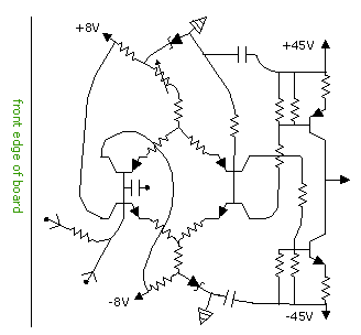
Below is a representation of the board pattern used for the current amplifier. Also shown is a 30 x 70 mm board with two current amplifiers on it, as it was used for the bridge amplifier. Two of these boards were attached to the back panel.   (Figure)

Current Amplifier Board.

Notice that there are two places where wires cross near the input. That is done by drilling holes and jumping wires over the top.

The resistors coming from the bases of the current sources attach directly to the collectors of the input transistors, and from there to the opposite rails. Attaching those resistors to ground would allow less voltage and less voltage change. But it doesn't really matter; and this way the ground doesn't have to be brought onto the board.

Sequence is important for positioning properly. First, the output transistors are marked; then the input transistors; then the current source transistors; and then the rest.
 
The board pattern for the quad input amplifier is shown below. The inverting input is watched for stray capacitance by leaving plenty of space between it and the collectors of the input transistors. Drill the hole patterns a little wider for those transistors. Two resistors jump over a line; and they are drilled wider also.   (Figure)

Board Pattern for Quad Input Amplifier


Soldering

Core type solder should be avoided at all times. Besides being messy and ineffective, it's slow promoting heat damage. Liquid rosin is very fast and efficient. It's applied with a toothpick, while the solder is picked up on the tip of the iron, which frees one hand.

However, for most purposes, citric acid disolved (saturated) in distilled water is much preferred over rosin. It doesn't create burnt carbon to coat surfaces, and it is easier to remove. It can conduct some current when humidity is high, so it needs to be removed with water. It can be found at pharmacies.

The board surface needs to be pretinned before adding components. Using citrate is not as easy as liquid rosin, but it works if the surface is cleaned well and buffed with a kitchen scratch pad. Then rub on the citrate with a cotton swab or paper towel. The citrate is self-cleaning and will eventually coat the surface uniformly.
 
Switches

The electronic switching is controlled with soft touch momentary switches. Nowdays, various types of posts are available on those switches. Back in the old days (1986), I had to glue pieces of quarter inch rods (from poteontiometer shafts) onto flat swithces using epoxy.

Where there are only two positions, such as the lines in and stereo, toggles are as convenient as electronic switching. It is primarily the multipositions of the gain select that make electronic switching valuable.

The soft touch switches are attached to perf board or pc board. The latter is stronger. Usually, more than one switch is attached to a single board. With the 90V amplifier, the bargraphs, a reset switch and six gain select switches were all attached to the same board. The board is attached to the front pannel with #2 or #4 screws. All of the wires coming off the board should go through a hole on the edge of the board for gathering them. Kyrnar wires, #30, are used. I tie them with string at 2" intervals. It's hard to make a gripping knot with string, so I make a half knot and add some instant glue. The wires than attach to headers on the main board. Machined pin sockets make the best headers. Wires solder into the top easily; and they have less exposed area than regular headers. The same are used for both male and female headers.
 
Back Panel

It is recomended that the entire current amplifier be constructed on an aluminum plate which is attached to the back panel for cooling. Then there is not a clutter of wires going back to the boosters; and the absence of long wires makes ringing easier to control. With the bridge amplifier, four boosters for each channel were attached to one aluminum plate.

The aluminum plates are elevated about 8mm or more by making a double bend on the sides. The boosters are attached directly to the aluminum using mica insulators, while everything else is on a pc board.

Aluminum plates for cooling the current amplifier can be made flat without bending by putting strips of quarter inch aluminum along two edges. There is then enough height for screws and fiber washers; but the heads of the screws must be downward. Without the need for bending, heavy aluminum can be more easily used. Use thickness of 1/8 or 3/16 inch, 3 or 5 mm, for high wattage. Drill the quarter inch aluminum, tighten it thoroughly and do not use spacers, because good heat conduction is needed. Use heatsink grease between metal slabs.
 
The leads for the boosters are protected from bending by attaching them to a board which is directly below them, as shown below. But rather than attaching the leads directly to the board, they are soldered to wires which come off the board. The ends of the wires then attach to the lines or loop over to other components. Two boosters have their leads pointed towards each other, because the collectors are linked, and the wires should be short.   (Figure)
 
Plates for Current Amplifiers

Two boards were used - one under the main board for insulating it. The lower one was also used for stabilizing the booster leads. The lower one was copper side up (mostly etched away), and the upper one was copper side down. The lower one was attached by screws on the ends; and the upper one was held in place by the wires only. A few wires were extra heavy for that purpose. The bridge amplifier could have been put in a little larger box; and then the dimensions of the plate could be a little larger.   (Figure)

Boxes


  Contents

     Page 1

     Page 2

     Page 3

     Page 4

     Page 5

     Page 6

     Page 7

Box for 10W Amplifier, Compact (Lab amp) 7 x 5.5 x 2.5 inches (W D H)

Box for Bridge Amplifier 12.25 x 7.5 x 3.25 inches. (W D H)

Box for 90V Amplifier 15.5 x 10 x 4.5 inches (W D H)


          dual headphone outputs, lower left

 
End View

There are few alternatives for the design of the boxes. They must be rectangular with fixed front and back panels; and the sides should open with the lid for accessibility. The few with such a design being sold in the catalogues are not very large; so they might have to be constructed from aluminum sheet metal, which is available from the heating and cooling shops, if a metal shop is not nearby.

Aluminum is sold as if it were fixed sizes (0.030, 0.040, 0.050 and 0.060 inches), but it has a continuous gradient of sizes and is put in one of those catagories, because the measuring devices have those notches on them. Size 40 is used for small boxes, 60 for large ones.

The edges for the main chasis must have a flange of about 1.5cm to strengthen the metal and for attaching the lid with sheet metal screws. The lid is a flat sheet with the ends bent down.

Fins are put on the back occupying all of the space that is not used for jacks. The bridge amp needed more cooling because of two inefficient transformers; so fins were also added to the sides of the lid. The 90V amp has 9 fin units (18 fins) on the back and none on the sides. Putting fins on the sides (lid) would allow the box to be smaller; but it was packed with components. When the switching complexity is reduced, the box can be smaller.

Fins are constructed by bending aluminum into a squared U shape. Each unit can be attached separately; or small ones can be placed inside large ones for fewer attachment points. Attach with 2 screws, #6 or #8.

With the 90V amp, most of the fins were 4" high; but two units were 3" high, so the input jacks could be placed above them. The output jacks and a switch went along the edge. With the bridge amp, fins were omitted in the center for the input jacks.

The outward length of the fins is 3", for the 90V amp, and 2", for the bridge amp. To determine their effectiveness, feel the temperature. The transformers are placed on the left side, and the volume controls on the right side, to keep them separated as much as possible. The transformers do not generally have to be shielded, because these amplifiers do not pick up noise easily. The toroid transformers do not emit much anyway. The bridge amp, having two transformers, picks up 3mV of hum at full volume. It can very faintly be detected at the speaker, because transformer hum is more audible than most types of noise. But it is so faint that shielding was not necessary. If shielding a transformer becomes necessary, putting roofing tin or aluminum around it is an improvement; but some noise will go around it.

Signal ground should be handled as a signal, which means not connecting the ground to just anything. The incoming lines use shielded wire within the box to prevent channel crossover, if not hum pickup. The shielding can be connected to the box where the lines come in. But ideally, the input jacks should be insulated, because more than one path to ground results in current edies which resonate with transformer hum which sometimes increases hum pickup a little. Metal RCA jacks can be insulated with shoulder washers.

The other end of the shielded wire for the lines in connects to the ground for the noninverting input of the amplifier and the volume control. If hum pickup is heard on the speakers, check the grounding procedure.

The LEDs on the front panels are small 3mm ones. Larger ones could usually be used. I attach them by carefully drilling holes of the right size, so they stay in with force. The holes must gradually be increased in size with the side of the drill bit. Making the holes larger and glueing the LEDs in with instant glue is a little easier; but to remove them, they must be drilled out.

I use toggles rather than slides, because they are easier to install and use than slides. Also, slides tend to be unreliable. A 3P2T toggle can be found at Mousers for the balance control.

After putting markings on as dry transfers, I cover them with clear tape, which works very good. The tape is nearly invisible and never gets damaged.
 
Harmonic Distortion

Harmonic distortion is so low in these amplifiers that it is not a significant consideration. The primary reason why HD is used as a statistic with audio amplifiers is because the output of the usual design oscillates. Removing the oscillation is difficult and expensive. If it is not entirely removed, the residual oscillation creates harmonics.

Tone controls can also create harmonics, but the problem primarily occurs with passive tone controls and should not be serious with active ones, if high impedance is avoided.

The current amplifier cannot produce harmonics, because it has no voltage gain, and it is too high in speed.

The quad input amplifier can be known to be extremely low in harmonics based on the circuitry. It has only two gain stages rather than the usual three; it has no internal capacitors, it is very low impedance and it is very high in speed. For these reasons, there is no better voltage amplifier for the purpose than the quad input amplifier.

Labor Saving

To minimize labor, potentiometers can be used for variable gain. To prevent the need for multiple input capacitors, the potentiometer can replace the feedback resistor rather than the input resistors. The current load is then calculated from the input resistor. Assuming a normal signal to be ±1 volt, and an optimum load to be 1mA, a 1K input resistor could be used, and the coupling capacitor would be 220µF.

Parts

If you are wondering where to get parts, the largest selection is Digi Key. The second is Mousers.

After getting their catalogs, you can verify availability of parts by searching the part number on their websites.


page one  |   contents

 
    1        2        3        4        5        6    
 

Electronics Home Page TOP     


  Contents

     Page 1

     Page 2

     Page 3

     Page 4

     Page 5

     Page 6

     Page 7